In most OEM manufacturing environments, fasteners are not selected as a matter of preference, branding, or differentiation. They are selected because they must satisfy a design that already exists.
In many cases, standard fasteners are the ideal solution. They are widely available, proven across industries, cost-effective, and well understood by engineers, buyers, and suppliers alike. When a standard fastener meets all dimensional, material, performance, and compliance requirements defined on a drawing, there is no advantage to pursuing an alternative.
However, OEM engineers and procurement teams are sometimes faced with a different reality: the drawing specifies a fastener that cannot be sourced from normal off-the-shelf inventory.
Understanding why certain fasteners fall outside standard supply chains and what that means for sourcing, lead time, cost, and feasibility is essential for OEMs navigating real-world production constraints.
Standard Fasteners: The Baseline Solution
Standard fasteners are mass-produced components manufactured to recognized industry specifications. Their value lies in consistency, availability, and predictability.
For many applications, standard fasteners offer immediate availability through established supply chains, proven performance characteristics, lower unit costs across most volumes, and straightforward replacement and serviceability.
The challenge does not arise because standard fasteners are inadequate it arises when they do not conform to the requirements defined on the drawing.
When Off-the-Shelf Is Not an Option
Fasteners fall outside standard inventory not because they are better, but because the design, constraints, or regulatory requirements demand something specific.
In OEM manufacturing, the drawing governs. If a fastener does not meet the specified geometry, material, origin, or compliance requirement, it is not a viable option regardless of how readily available it may be elsewhere.
Print-Specific Fasteners Are Not an Upgrade – They Are a Requirement
In most cases, the design already dictates the fastener, no stocked alternative exists, and the part must be manufactured to customer print.
How G-Fast Fits Into This Reality
G-Fast supports OEMs operating within print-driven manufacturing environments by providing structured feasibility evaluation not design services.
Our engineers review customer drawings and specifications for manufacturability, feasibility, and cost efficiency. Any recommendations are advisory only and must be approved by the customer’s engineering team and reflected on an updated print prior to production.
Standard vs. Print-Specific: A Practical Summary
Working With G-Fast
If your application calls for a fastener that cannot be sourced from standard inventory, G-Fast can assist by evaluating the feasibility of your specified part. You may submit a print for review or request a quote to begin the evaluation process.
Consideration
Standard Fasteners
Print-Specific Fasteners
Basis
Industry standard
Customer drawing
Inventory status
Stocked
Manufactured to order
Design definition
Defined by standard
Defined by customer print
Lead time
Typically short
Extended
Cost structure
Optimized through scale
Specification-driven
Supplier role
Fulfillment and sourcing
Feasibility evaluation to print
Steve Greenberg
Steve Greenberg has over 35 years of experience in the fastener industry. His expertise includes interpreting and engineering prints, understanding the customer’s special requirements and delivering economical quoting and manufacturing of custom fasteners and components for diverse applications.
Known as the supply chain “hero” for solving fastener sourcing challenges, Steve shares practical insights with the customer to arrive at the best options. By taking into consideration, material selection, and optimal manufacturing methods, G-Fast can arrive at a precision engineered finished fastener or component as required for his customer’s assembly or finished product.
The G-Fast blog will share examples of completed projects, providing valuable guidance to engineers and purchasing agents seeking reliable, innovative fastening solutions.
When precision alignment and secure fastening matter, selecting the appropriate pin type can mean the difference between reliable performance and costly equipment failure. Understanding the key differences between pin designs, materials, and applications helps engineers specify the optimal solution for their specific needs.
Understanding Pin Fastener Fundamentals
Unlike threaded fasteners, pins provide non-threaded alignment and positioning solutions. They excel in applications requiring precise component location, shear load distribution, and quick assembly or disassembly capabilities. Their primary functions include maintaining accurate alignment tolerances, preventing rotation in mechanical linkages, and providing easy maintenance access in industrial equipment.
Comparing Common Pin Types
Solid Cylindrical Designs
These precision-ground pins offer tight diameter tolerances essential for accurate component alignment. They work best in tooling systems, load-bearing joints, and high-shear applications where dimensional accuracy is critical. Engineers typically specify these for press-fit installations requiring interference fits or precision slip-fit assemblies with secondary retention.
The key consideration is tolerance class selection. Tighter tolerances ensure proper fit but increase manufacturing costs. Applications with less critical alignment requirements can use standard tolerance grades for cost savings.
Headed Pin Solutions
Adding a head creates a built-in installation stop, simplifying assembly processes and ensuring consistent positioning. This design eliminates the need for additional washers or retaining hardware in many applications. Common in construction equipment, automotive linkages, and adjustable assemblies, headed configurations speed installation while maintaining security.
Various head styles serve different purposes. Shoulder designs provide precise depth control, while flanged heads offer larger bearing surfaces for softer materials. The head also facilitates easier removal during maintenance procedures.
Quick-Release Mechanisms
For equipment requiring frequent adjustments or regular maintenance access, quick-release pins eliminate the need for tools during assembly and disassembly. Ball-lock, detent, and spring-loaded designs offer varying levels of retention strength and release force requirements.
These solutions excel in aerospace interior panels, industrial workstations, and military equipment where rapid configuration changes are necessary. The trade-off is typically higher cost compared to standard pin designs.
Material Selection Considerations
Stainless Steel Applications
When corrosion resistance is paramount, stainless steel grades provide reliable performance in challenging environments. Type 304 (18-8) stainless offers general-purpose corrosion protection suitable for outdoor installations and moisture exposure. Type 316 stainless provides enhanced resistance for marine environments and chemical processing applications.
Medical device manufacturing and food processing equipment often require stainless specifications to meet sanitation standards and prevent contamination. The material’s non-magnetic properties also benefit certain electronic and aerospace applications.
Hardened Steel Performance
Heat-treated pins deliver superior wear resistance and fatigue life in demanding conditions. Hardness levels typically reach Rockwell C 60 or higher, providing dimensional stability under repeated loading cycles. High-speed automated equipment, precision tooling systems, and heavy machinery benefit from hardened specifications.
The increased hardness comes with material brittleness considerations. Applications with impact loading or extreme vibration may require careful evaluation of hardened versus unhardened options.
Alloy Steel Options
Alloy grades like 4140 and 4340 offer optimized strength-to-weight ratios for performance-critical applications. These materials provide heat treatment flexibility, allowing manufacturers to achieve specific mechanical properties through controlled processing. Aerospace and high-performance automotive systems frequently specify alloy compositions for their superior engineering characteristics.
Industry-Specific Requirements
Aerospace Standards
Precision tolerance control, complete material traceability, and rigorous testing protocols define aerospace pin specifications. Dimensional accuracy often requires tolerances within ±0.0002 inches. Weight optimization drives material selection while maintaining required strength characteristics. Applications include control linkages, interior panel fastening, and landing gear components.
Automotive Manufacturing
High-volume production compatibility and cost optimization guide automotive pin selection. Parts must withstand vibration, temperature cycling, and extended service life while meeting aggressive cost targets. Common uses include suspension linkages, engine mounts, and body panel alignment systems.
Heavy Equipment Needs
Extreme load capacity and field replaceability characterize heavy equipment pin requirements. Corrosion protection and impact resistance ensure reliable operation in harsh outdoor conditions. Hydraulic cylinder connections, boom pivot points, and bucket assemblies depend on robust pin designs.
Making the Right Choice
Successful pin selection balances performance requirements, cost considerations, and application-specific demands. Consider load characteristics, environmental exposure, tolerance requirements, and maintenance accessibility when evaluating options.
Working with experienced fastener manufacturers provides access to application engineering support, material recommendation guidance, and manufacturing method selection expertise. Technical partners help optimize designs for cost-effectiveness without compromising performance.
Whether your project involves aerospace precision, automotive volume production, or industrial durability requirements, understanding these fundamental selection criteria enables informed specification decisions that enhance assembly reliability and long-term performance.
Need expert guidance on pin specifications for your application? G-Fast combines 35+ years of fastener manufacturing expertise with comprehensive engineering support. Our USA-based facilities deliver custom solutions from prototype through production. Explore our precision pin capabilities or contact our technical team for application-specific recommendations.
Steve Greenberg
Steve Greenberg has over 35 years of experience in the fastener industry. His expertise includes interpreting and engineering prints, understanding the customer’s special requirements and delivering economical quoting and manufacturing of custom fasteners and components for diverse applications.
Known as the supply chain “hero” for solving fastener sourcing challenges, Steve shares practical insights with the customer to arrive at the best options. By taking into consideration, material selection, and optimal manufacturing methods, G-Fast can arrive at a precision engineered finished fastener or component as required for his customer’s assembly or finished product.
The G-Fast blog will share examples of completed projects, providing valuable guidance to engineers and purchasing agents seeking reliable, innovative fastening solutions.
Industrial nuts may seem like small components, but they play a critical role in the strength, safety, and reliability of mechanical assemblies across every industry. Whether used in construction, heavy machinery, automotive, marine, or custom-engineered systems, the right nut ensures secure joints, prevents failures, and supports long-term performance in demanding environments.
With dozens of nut types, material options, and grade specifications available, selecting the correct one can be challenging. This guide walks you through the essential factors material, grade, type, coating, standards, and usage conditions—so you can make confident, application-specific decisions.
Why Nut Selection Matters
A nut does more than just hold a bolt in place. The wrong type or grade can lead to premature corrosion, joint loosening, mechanical failure, or safety hazards. Industrial environments often involve vibration, temperature changes, chemical exposure, or extreme loads making it essential to choose nuts engineered for durability, stability, and compliance with industry standards.
Understanding Materials & Grades
Carbon Steel Nuts
Carbon steel is the most widely used nut material because of its strength and cost-effectiveness. It is ideal for general-purpose applications but should be paired with appropriate coatings for corrosion protection.
Alloy Steel Nuts
Alloy steel nuts offer higher tensile strength and are suitable for high-load, heavy-duty equipment. They are commonly used in industrial machinery, structural frameworks, and high-pressure systems where performance and fatigue resistance matter.
Stainless Steel Nuts
Stainless steel nuts provide excellent corrosion resistance, making them a top choice for outdoor, marine, chemical, and high-humidity environments. Grades like 304 and 316 offer varying levels of corrosion resistance, with 316 favored for coastal or chemical applications.
Understanding Grades
Grades indicate the mechanical strength of the fastener. Higher grades mean higher tensile strength and load capacity. For example:
Always match the nut grade with the corresponding bolt grade to ensure optimal joint performance.
Types of Industrial Nuts and Their Applications
Different nut types serve different functional needs. Some of the most essential include:
Hex Nuts
The most common and versatile, ideal for general industrial use.
Heavy Hex Nuts
Thicker and wider than standard hex nuts, designed for high-strength bolts and structural applications.
Lock Nuts
Includes nylon insert lock nuts, prevailing torque nuts, and all-metal lock nuts. These prevent loosening caused by vibration and dynamic loads.
Flange Nuts
Built-in washer distributes load evenly and reduces the need for additional components.
Coupling Nuts
Used to join two male-threaded components, ideal for long rod assemblies or extended connections.
Cap, Acorn, and Specialty Nuts
Used for decorative finishes, safety protection over exposed threads, or special-purpose equipment.
Choosing the right type ensures that the nut performs effectively under the specific mechanical and environmental stresses of your application.
Manufacturing Quality & Standards to Look For
High-quality nuts undergo controlled manufacturing processes such as cold forging, thread rolling, precision machining, heat treatment, and surface coating. Quality fasteners also comply with industry standards such as:
ASTM
ISO/DIN
SAE
Certified products guarantee consistency, load integrity, and safety compliance. Additionally, choosing a U.S.-manufactured nut ensures better material traceability and strict quality control.
How to Select the Right Nut for Your Application
When choosing a nut, consider the following:
Load and Stress Requirements
High-load or structural applications require high-grade alloy or heavy-hex nuts. Underestimating load capacity can compromise equipment safety.
Environmental Conditions
For wet, corrosive, or chemical environments, stainless steel or coated carbon steel is essential.
Vibration and Movement
Use lock nuts or prevailing torque nuts in high-vibration machinery, automotive assemblies, and rotating equipment.
Temperature Exposure
High temperatures can weaken certain metals or coatings. Choose materials with heat-resistant properties for ovens, engines, or industrial furnaces.
Coating and Surface Treatment
Zinc plating, galvanization, phosphate coating, or specialized corrosion-resistant coatings extend fastener life in harsh conditions.
Installation & Maintenance Best Practices
Even the strongest nut can fail without proper installation. Consider the following:
Always tighten to the recommended torque value.
Use washers where needed to distribute load evenly.
For vibration-prone systems, incorporate locking mechanisms.
Inspect periodically for signs of corrosion, thread wear, or loosening.
Replace nuts showing any deformation or damage rather than reusing them.
Proper installation reduces failure risks and prolongs equipment life.
Final Thoughts
Industrial nuts may be small, but their impact on safety, durability, and performance is enormous. Choosing the right material, grade, type, and coating ensures secure assemblies that withstand demanding conditions. Whether you need nuts for machinery, construction, fabrication, automotive, or heavy industrial applications, informed selection is key.
If you’re looking for high-quality, USA-made industrial nuts with superior reliability and strict manufacturing standards, G-Fast provides a full range of fastener solutions tailored to your application needs.
In OEM manufacturing, fastener selection is rarely about preference. It is dictated by design constraints, assembly realities, and service requirements.
Within the socket screw family, engineers commonly navigate between standard socket head cap screws, button head socket cap screws, and low head socket cap screws. These fasteners share a common functional baseline: they bear on the surface beneath the head, and length is measured from under the head rather than from the top.
The Shared Baseline: Bearing Surface and Length Measurement
Unlike flat head socket screws, which are designed to seat in a countersunk feature and are measured from the top of the head, cylindrical socket head profiles transfer load through the bearing surface under the head. This shared geometry keeps the design problem focused on clearance, torque access, and installation mechanics not countersink geometry.
Where the Profiles Diverge: Head Height and Torque Access
Standard socket head cap screws often associated with the classic 1960-era socket head design offer the tallest head height and deepest socket engagement. They provide the greatest torque access and remain the baseline solution when vertical clearance is not constrained.
Button head socket cap screws reduce head height significantly while maintaining a bearing surface under the head. This profile is commonly specified when vertical clearance is limited but torque requirements remain moderate.
Low head socket cap screws further reduce head height to address extreme clearance constraints. This reduction comes with shallower socket depth and reduced torque capacity, making low head designs appropriate only when space limitations outweigh torque demands.
Driver Geometry Considerations
Most cylindrical socket head profiles are available with traditional hex sockets as well as 6-lobe internal drives (Torx®-compatible). The 6-lobe geometry uses an equivalent tooling form and can provide improved torque transfer with reduced cam-out, particularly in lower-profile head designs where socket depth is limited.
Internal spline drives may also be specified in certain proprietary or high-torque applications, but they are far less common than hex or 6-lobe internal drives in general OEM assemblies.
Side-by-Side Comparison: Cylindrical Socket Head Profiles
Consideration
Standard Socket Head
Button Head
Low Head
Bearing surface
Under head
Under head
Under head
Length measurement
Under head
Under head
Under head
Relative head height
Tallest
Lower
Lowest
Socket depth
Deep
Shallower
Shallowest
Torque access
Highest
Reduced
Most limited
Driver options
Hex, 6-lobe & spline
Hex, 6-lobe & spline
Hex, 6-lobe & spline
Print-Driven Reality in Socket Screw Selection
While standard socket screws are widely available from inventory, many applications specify non-standard lengths, materials, or tolerances that require print-specific manufacturing. At that point, the fastener is no longer a commodity selection but a specification-driven component.
How G-Fast Fits Into Print-Specific Socket Screw Applications
G-Fast reviews customer drawings for manufacturability, feasibility, and cost efficiency. We work strictly from approved customer prints and do not provide design services. When appropriate, we may identify manufacturing considerations or alternative processes for customer review. Any recommendation must be approved by the customer’s engineering team and reflected on an updated print prior to production.
If your application requires socket screws outside standard inventory, submit your print for review to begin the evaluation process.
Steve Greenberg
Steve Greenberg has over 35 years of experience in the fastener industry. His expertise includes interpreting and engineering prints, understanding the customer’s special requirements and delivering economical quoting and manufacturing of custom fasteners and components for diverse applications.
Known as the supply chain “hero” for solving fastener sourcing challenges, Steve shares practical insights with the customer to arrive at the best options. By taking into consideration, material selection, and optimal manufacturing methods, G-Fast can arrive at a precision engineered finished fastener or component as required for his customer’s assembly or finished product.
The G-Fast blog will share examples of completed projects, providing valuable guidance to engineers and purchasing agents seeking reliable, innovative fastening solutions.
In most manufacturing environments, fastener selection is not a matter of preference. It is driven by what the design and the assembly process require.
Both solid rivets and semi-tubular rivets are well-established fastening solutions. Each has a defined role, and both are widely used across industries.
The distinction between them becomes important not because of features or materials, but because installation mechanics, equipment limits, and material behavior place real constraints on how a joint can be formed.
The Real Difference: Installation Energy and Deformation Control
The fundamental distinction between solid and semi-tubular rivets is how much material must be displaced during installation. Solid rivets require the deformation of a fully solid shank, demanding higher installation force and robust tooling.
Semi-tubular rivets reduce the amount of material that must be upset during installation by introducing a controlled hollow at the tail end.
Where Semi-Tubular Rivets Are Specified by Necessity
Semi-tubular rivets are typically specified when installation constraints drive the design, such as limited-force equipment, high-speed automation, or sensitive materials.
Strength Is Not Debated – It Is Designed Around
It is well understood that a semi-tubular rivet will not match the shear strength of a solid rivet of the same diameter. This difference is accounted for during joint design.
Print-Driven Reality: When Rivets Are Not Off-the-Shelf
At that point, the rivet becomes a print-specified component, and the sourcing discussion shifts from selection to feasibility.
Manufacturing Process and Quantity Considerations
Cold heading is commonly used for medium- to high-volume rivets where geometry and material are compatible with forming limits.
Machining may be the practical choice for lower volumes, complex geometries, or materials that do not lend themselves to forming.
In cold heading operations, forming dies are considered perishable production tooling, are not customer-owned, and are typically absorbed into production economics rather than charged as a separate tooling item.
Side-by-Side Comparison: Solid vs. Semi-Tubular Rivets
Consideration
Solid Rivets
Semi-Tubular Rivets
Installation force
High
Lower
Material deformation
Full solid shank
Partial hollow collapse
Typical applications
High-load, structural joints
High-speed, controlled installation
Shear strength
Higher
Lower (designed accordingly)
Equipment requirements
Robust tooling
Reduced-force tooling
How G-Fast Fits Into Print-Driven Rivet Applications
G-Fast reviews customer drawings for manufacturability, feasibility, and cost efficiency. We work strictly from approved customer prints and do not provide design services. If your application requires rivets outside standard inventory, submit your print for review to begin the evaluation process.
Steve Greenberg
Steve Greenberg has over 35 years of experience in the fastener industry. His expertise includes interpreting and engineering prints, understanding the customer’s special requirements and delivering economical quoting and manufacturing of custom fasteners and components for diverse applications.
Known as the supply chain “hero” for solving fastener sourcing challenges, Steve shares practical insights with the customer to arrive at the best options. By taking into consideration, material selection, and optimal manufacturing methods, G-Fast can arrive at a precision engineered finished fastener or component as required for his customer’s assembly or finished product.
The G-Fast blog will share examples of completed projects, providing valuable guidance to engineers and purchasing agents seeking reliable, innovative fastening solutions.
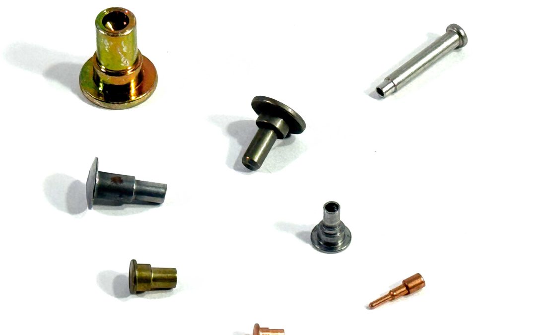
Shoulder rivets are used in assemblies where controlled spacing, rotation, or alignment is required often in pivoting or rotating mechanisms where a standard rivet or screw cannot maintain consistent geometry.
In most applications, shoulder rivets are designed by the customer’s engineering or industrial design team to meet a specific functional requirement. Once that design is defined, the challenge becomes sourcing or manufacturing the rivet exactly as specified.
While some shoulder rivets may resemble stocked components, there is no true universal standard for shoulder rivets. Geometry, shoulder length, bearing surface, and tolerances are inherently application specific. As a result, most shoulder rivets are custom fasteners manufactured to customer print.
Standard vs. Print-Specific Shoulder Rivets
Standard shoulder rivets may be available when dimensions, materials, and tolerances align with existing inventory. When they do, they offer speed and cost efficiency.
Print-specific shoulder rivets exist because the drawing requires geometry or performance that standard inventory does not provide. This is not an upgrade or optimization choice the design governs.
When Shoulder Rivets Become Print-Specific
A shoulder rivet typically becomes print-specific when requirements include:
Non-standard shoulder diameters
Shaft lengths dictated by assembly stack-up
Bearing surfaces with specific profiles
Tolerances tighter than stocked parts provide
Material or origin requirements not met by inventory
When these conditions exist, substituting a stocked part is not acceptable without redesign. The rivet must be manufactured exactly as specified.
Manufacturing Process and Quantity Considerations
Shoulder rivets can be produced using different manufacturing processes depending on quantity, size, geometry, and material.
At higher volumes, shoulder rivets may be produced using cold heading or, for larger geometries, hot forging. These processes are efficient and repeatable when quantities justify tooling and setup.
For lower volumes, prototypes, or designs with complex geometry or material constraints, machining is often the most practical manufacturing method.
Cold Heading vs. Machining: Practical Manufacturing Considerations
Consideration
Cold Heading / Forming
Machining
Typical quantity range
Medium to high volumes
Low to medium volumes; short runs
Material suitability
Limited to formable materials
Broad material range
Geometry constraints
Limited by forming and upset ratios
Highly flexible geometry
Tolerance capability
Consistent within forming limits
Tight tolerances achievable
Tooling requirement
Perishable production tooling
Minimal or no dedicated tooling
In cold heading operations, forming dies are considered perishable production tooling, are not customer-owned, and are typically absorbed into production economics rather than charged as a separate tooling item. This principle applies broadly to cold-headed rivets, semi-tubular rivets, screws, and similar fasteners.
How G-Fast Fits Into Print-Specific Shoulder Rivets
When appropriate, we may identify alternative materials or manufacturing processes for consideration based on feasibility. Any recommendation is advisory only and must be reviewed, approved, and reflected on an updated print by the customer’s engineering team prior to production.
Working With G-Fast
If your application requires a shoulder rivet that cannot be sourced from standard inventory, G-Fast can evaluate your print-specific requirement and provide clear feedback on feasibility, lead time, and cost drivers. Submit your drawing for review to begin the evaluation process.
Steve Greenberg
Steve Greenberg has over 35 years of experience in the fastener industry. His expertise includes interpreting and engineering prints, understanding the customer’s special requirements and delivering economical quoting and manufacturing of custom fasteners and components for diverse applications.
Known as the supply chain “hero” for solving fastener sourcing challenges, Steve shares practical insights with the customer to arrive at the best options. By taking into consideration, material selection, and optimal manufacturing methods, G-Fast can arrive at a precision engineered finished fastener or component as required for his customer’s assembly or finished product.
The G-Fast blog will share examples of completed projects, providing valuable guidance to engineers and purchasing agents seeking reliable, innovative fastening solutions.